
3. Project development
Developing a CCS chain with CO2 capture, transport by ship and geological storage is technically feasible and safe. Competent contractors and suppliers can be mobilized and a CCS chain can be developed with limited use of new technology. The London Protocol has for years been a barrier for cross- border transport and storage of CO2. However, in 2019 the parties to the London Protocol agreed on a temporary amendment allowing export of CO2 for the purpose of storage offshore. Aside from this, no regulatory showstoppers have been identified so far.
Design basis
As a tool to frame the overall project and the various sub-projects along the CCS chain, Gassnova has developed and maintained an overall Design Basis document.
The Design Basis has been developed in close cooperation with the industrial partners following a philosophy of keeping the number of requirements to a minimum.
This allows freedom for each sub-project, while also ensuring that the sub-projects will fit together as a whole to make up the CCS chain. Few requirements leave things to the interface development performed jointly by the partners, which is likely to give the most “industrial” solutions.
Specifically, the parameters that have been governed by the Design Basis during the FEED studies are:
- Target CO2 capture rate of 400,000 tonnes of CO2 per year per capture site
- Technical design life (25 years)
- Placement of the battery limit between capture and transport/storage
- Overall philosophies for HSE, design and operation
- CO2 specification and export conditions at the capture plant export terminals
- Online measurement of impurities in CO2 during export from capture site
- Dimensioning criterion for the interim storage tank capacity at the capture plant export terminals
- Maximum ship dimensions for selection of berth
- Capacity of onshore power supply
- Transport ship propulsion type
- Design capacity of CO2 receiving terminal (1,500,000 tonnes of CO2 per year)
- Vapour return system
Due to a lack of experience from comparable CCS chains around the world, Gassnova chose not to develop firm requirements for availability or uptime for the total CCS chain or for each part of the chain. The only exception is that capture plant availability should be above 85%, which is not very challenging. Based on the estimates from the FEED studies, the overall availability of the CCS chain is expected to be around 92-93%.
The philosophy of keeping the number of requirements as low as possible in the overall Design Basis has worked as intended, allowing the sub-projects to develop as each partner has seen fit. This has led to few significant changes and has maximized the alignment between the project and each partner.
Transport of CO2 in a liquid state implicitly adds purification of the CO2 “for free”, as many impurities are naturally removed in the liquefaction process. Studies show that relaxing the specification would only give minor savings in capture costs. The CO2 specification for a CCS chain based on transport in gaseous/ dense phase will require a different specification.
Introducing requirements for overall availability, as well as the availability of each part of the CCS chain, would have made it easier for the partners to optimize the design of their facilities. However, this “top-down” approach would also introduce a risk of setting the wrong target, as the development of a CCS chain does not yet have any clear business
Capture technology selection
The technology used for capturing CO2 from a flue gas is often unproven or previously used on different gases or under different conditions.
Selection of the right technology to use is a central choice for a CCS project and depends on many factors such as the characteristics of the CO2 emission source, available utilities, whether a large or small fraction of the CO2 is to be captured, etc.
The maturity of available technologies is also an important factor since qualification of new technology always is uncertain and requires use of additional resources during the project development (see chapter 03).
To minimize net present cost or max net present value, will generally be the objective when selecting technology. Constraints may be the allowable emissions of degraded amine products, available capacity in the downstream CCS chain, etc. However, in practice it may prove difficult to produce reliable cost estimates if the technology selection is done at an early stage in the project. Other objectives besides low cost may also be relevant. Both Fortum Oslo Varme, Heidelberg Materials and Yara put emphasis on avoiding time and resource demanding qualification programs when selecting capture technology.
When selecting capture technology, it is important to consider aspects like:
- Access to heat and electricity.
- Techno-economic assessment covering different types of technologies & technical solutions (e.g. change in operating conditions of host plant and required pre-treatment of flue gas). Even within the category of amine technology there are many amines with different pros & cons.
- For amine technology it is particularly important to establish reliable predictions for expected emissions of amines and amine degradation products to air. Remember that each amine is different and that countries have different requirements to what is acceptable emissions!
- Conditioning for transport and/or storage (liquefaction, compression, purification, etc.) is a significant part of the CCS chain and is affected by the choice of capture technology.
- Different technologies may favour partial or full capture.
- Means of transport to storage site (if not already given as a boundary condition).
- Pros and cons of using proprietary technology, which will heavily influence later procurement strategies.
- Use of unproven or new technology will add risk and uncertainty and will require technology qualification. Experiences from design and operation of relevant references are key elements when assessing a technology.
- Ability of technology provider to issue and back up performance guarantees.
Fortum Oslo Varme, Heidelberg Materials, and Yara put different weightings on these points (and other criteria that they consider important). This is reflected by the type of technology selected and the timing of the selection, as shown in Figure 3.
When planning to use amine technology for capture, it is important to quantify the emissions of potentially carcinogenic substances into the air and to model how these are dispersed in the surrounding environment. It is advisable to involve personnel and suppliers with specific competence and experience with CO2 capture at an early stage, including understanding of local environmental regulations. A “toolbox” for amine technology has been developed by Gassnova and is available at https://ccsnorway.com/
The capture technology selection process is like other major decisions that are typically taken in the concept selection There are no major differences compared to other conceptual decisions, but certain aspects should be kept in mind (as listed above).
Selecting capture technology before the concept selection phase will narrow down the available choices too early, restriction options in the next phase of the project. This is likely to reduce the overall value of the project by increasing the cost or reducing the benefits.
When considering using proprietary capture technology, it is important to acknowledge that this will make it challenging to obtain competitive bids for your project in a later stage. This is particularly relevant if the technology provider has an exclusive partnership with, or is owned by, an engineering contractor. It is highly advisable to early develop a contract strategy that ensures competition for the detailed engineering and construction of the major parts of the scope. The fact that Fortum Oslo Varme and Heidelberg Materials have competed to be part of the CCS chain has partly compensated for the lack of competition on the main contracts within their own scope.
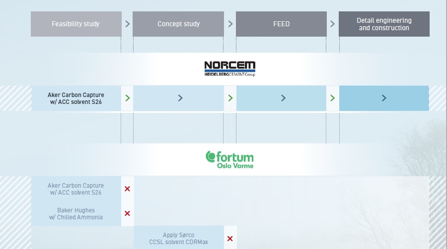
Different engineering contractor and technology provider options explored by the industrial partners.
Maturation of the underground storage
The potential for geological storage of CO2 in Norway is concentrated on the Norwegian Continental Shelf due to lack of suitable geology on land. The Norwegian Petroleum Directorate has published an extensive description of this potential in a CO2 Storage Atlas (2014) that maps out the options available in depleted hydrocarbon fields and saline aquifers.
When maturing a potential CO2 storage site in Norway the focus has been on:
- assessment of the entire storage complex and its boundaries;
- assessment of the integrity of the seal;
- simulations of CO2-plume migration within the storage complex;
- assessment of the pressure development in the reservoir;
- how the dissolution of CO2 evolves in the reservoir;
- how to handle possible pressure increase far above initial pressure, and
- time perspective of thousands of years.
Potential sites with limited data availability or low degree of maturation, long distance to shore, or uncertain seal properties were excluded from further investigation. This is in line with the ISO standard for geological storage of CO2 (ISO 27914, 2017) that Norway helped to develop.
The Northern Lights storage site within the area referred to as Aurora will be the third CO2 storage site to be developed in Norway. The CO2 reservoir selection processes for the Sleipner and Snøhvit fields were constrained by the field development plans for their associated petroleum projects, but the selection process for Northern Lights has been different since it is not tied to petroleum field development.
The selection process carried out by Northern Lights is the most recent stage in a site screening process that began on the Norwegian continental shelf in 2007 and will carry on into the future as additional CO2 storage sites are developed by Northern Lights and other operators. The key stages in this site screening process are described in chronological order.
The choice of CO2 storage site was changed during the concept This caused a delay to the concept study and has generated additional pipeline cost for the project by moving to the Aurora area, further offshore. The decision was justified with new information that came to light during the study work which increased the concerns about possible pressure connection with the Troll field. A key learning point is the need for flexibility in the concept selection phase and the availability of one or more back-up storage locations that have been de- risked to some extent already, as was the case with the Aurora area.
This storage site was chosen to minimise potential legal and commercial complications by storing CO2 in a saline aquifer outside of existing hydrocarbon licence areas. This has been a critical success factor in order to complete the concept and FEED studies in a timely manner. The re-use of depleted oil and gas fields may also generate additional cost related to the treatment of legacy wells.
Longship is being developed within the legal framework of Norwegian CO2 storage regulations and these have proven to be fit for purpose. The risk management approach taken by the project team has been broadly consistent with that described by ISO 27914:2017 ‘Carbon dioxide capture, transportation and geological storage – Geological storage’. This is recommended as a reference source for managing risks and opportunities associated with CO2 storage.
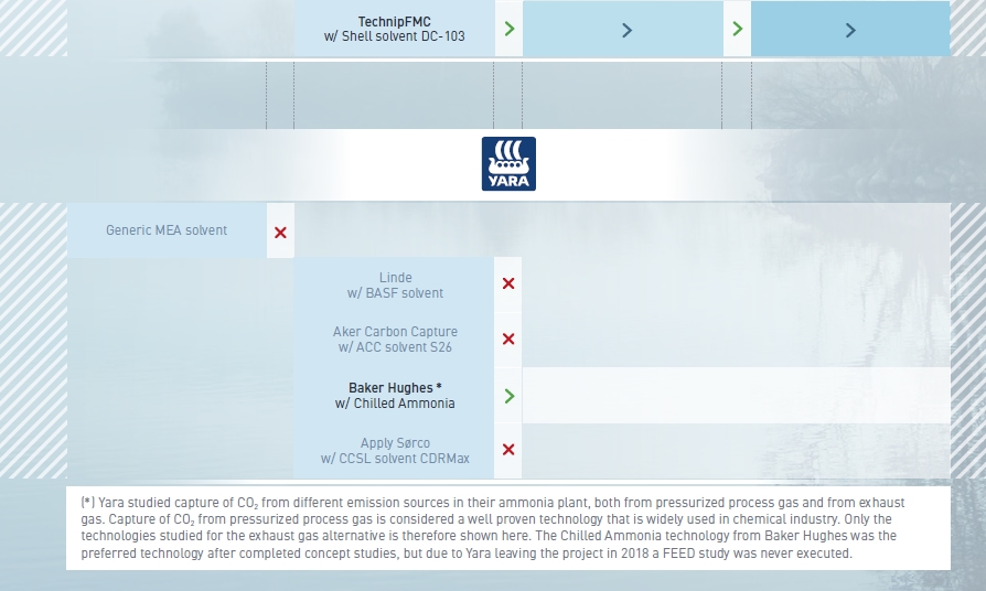
Figure 4: Three areas studied in the feasibility study completed in 2016.
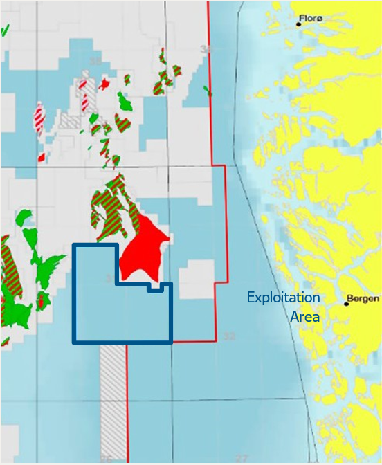
Figure 5: Map showing the Exploitation Area in blue
| 2007 | The Norwegian Petroleum Directorate (NPD) began mapping CO2 storage resources. A report prepared for the MPE by Gassnova, Gassco and NPD concluded that CO2 can be stored safely offshore Norway. | ||
| 2010 | One North Sea Report presents a study into North Sea cross-border CO2 transport and storage where the potential for CO2 emissions from the industry around the North Sea Basin and potential storage sites capacity was analysed. | ||
| 2011 | MPE invited the industry to nominate promising areas in the North Sea and Norwegian Sea for exploration for potential reservoirs for permanent storage of CO2 from the Mongstad refinery. | ||
| 2012 | Gassnova presented a study to the MPE after analysis of the Johansen Formation and the Upper Jurassic Sognefjord Formation. | ||
| 2013 | The Government pointed out a new direction for CCS. The development of full-scale CO 2 capture at Mongstad was discontinued. | ||
| 2014 | The Norwegian regulations for CO2 transport and storage were passed into law and the NPD published a CO2 Storage Atlas for the entire Norwegian continental shelf. | ||
| 2015 | Gassnova delivered a pre-feasibility study for a new CCS value-chain in Norway to the MPE. Gassnova was granted funding to initiate a series of CCS feasibility studies based on results of the pre-feasibility study. | ||
| 2016 | MPE published the results of the feasibility studies carried out by Gassnova in partnership with Gassco and the industrial partners. These confirmed that it would be possible realize a full-scale CCS project in Norway and through Gassnova MPE initiated concept and FEED studies with the industrial partners. Equinor proposed three possible areas for CO2 storage (see Figure 4) and recommended one of them, Smeaheia, for further study. | ||
| 2017 | Equinor formed the Northern Lights partnership with Shell and Total. Gassnova coordinated the studies with the two CO2 capture sites. Northern Lights decided to change storage location within the Horda Platform region from Smeaheia area east of Troll to the Johansen Formation south of Troll and made use of previous state funded work and seismic data from 2008-2014. The relevant reservoir intervals in the Smeaheia area were found to have a possible pressure connection with the giant Troll oil and gas field that could negatively affect the density of CO2 stored there in the long term and this risk is now being investigated further by Equinor research. | ||
| 2018 | MPE announced the first exploitation licensing for CO2 storage within area south of the Troll field. This area included the area of interest for CO2 storage in the Johansen Formation. | ||
| 2019 | MPE granted Equinor an exploitation permit for CO2 storage, EL001 on behalf of Northern Lights, as shown in Figure 5. This is the area referred to as Aurora. | ||
| 2020 | The first exploration well, 31/5-7, Eos, was drilled in the licence. The well showed good potential for CO2 storage. The Northern Lights partnership submitted a development plan for EL001 to MPE. |
Energy input and carbon footprint
CCS is known to be energy-intensive, and without any heat integration on the capture side, the total energy input required by the Norwegian CCS chain would be around 1.2–1.5 MWh/tonne CO2. About 2/3 of this is needed as heat, while the rest is electricity and fuel for the ship. The energy required for the ship transport and for storage is marginal compared with the energy input required for capture, in particular the amine capture process and downstream liquefaction facility.
With efficient heat integration, as studied and developed by both Heidelberg Materials and Fortum Oslo Varme, it has been possible to reduce the energy requirement for the chain by as much as 40-75%.
The diagrams Figure 6 and Figure 7, show the energy input along the CCS chain for both Heidelberg Materials and Fortum Oslo Varme with and without energy saving from extensive integration. The heat integration can be done both between the production plant and capture process and between the capture process and liquefaction plant. Due to the differing nature of the Heidelberg Materials and Fortum Oslo Varme production plants it is not possible for Fortum Oslo Varme to extract as much energy from the waste-to-energy plant as Heidelberg Materials can from the cement production.
In order to verify that Longship will store much more CO2 than what will be emitted from the construction and operation of the chain, the carbon footprint was calculated. The carbon footprint is expressed as the CO2 that is emitted in order to capture, transport and store one tonne of CO2, taking the whole lifetime of the project into consideration. The main results are shown in Table 1. A dedicated report has been published by Gassnova* and an article with updated results will be published for the conference GHGT-15.
A third party developed an efficient setup for collecting the necessary input data from the project, following ISO 14040 “Life Cycle Analysis – principles and framework” and ISO 14044 “Life Cycle Analysis – requirements and guidelines”. For each building block in the CCS chain, all project phases were included, from construction to decommissioning and post-closure of the storage. For each phase, the CO2 emissions from the use of fuel, energy, chemicals, materials and transport were calculated.
The main reason to calculate the carbon footprint of Longship was to document that the footprint will be low and very much lower than the amount of CO2 stored. In fact, the calculations show that the carbon footprint will be lower for than other CCS projects reported in the literature**. This can be attributed to extensive use of waste heat, Norwegian electricity mix with low CO2 footprint, and a high focus on using low footprint energy and fuel alternatives wherever possible.
Heidelberg Materials has a lower carbon footprint than Fortum Oslo Varme, mainly due to the opportunity to utilize the excess heat from the cement production. At Fortum Oslo Varme’s waste-to-energy plant the heat is already used to produce electricity and provide district heating, which have prompted the use of heat pumps to compensate for the heat needed in the capture process.
* A dedicated report on the CO2 footprint as calculated after the FEED studies is available at https://ccsnorway.com/
** R. M. Cuellar-Franca and A. Azapagic, Carbon capture, storage and utilization technologies: A critical analysis and comparison of their life cycle environmental impacts, Journal of CO2 utilization 9, 2015, p. 82-102
The capture plant has by far the biggest energy input requirement in the CCS chain. Since the CO2 will be transported and injected in liquid form, the transport and storage parts of the chain only require a few percentages of the total energy
For capture plants efficient heat integration is crucial, and it is highly recommended to perform detailed studies to find the optimum degree of Both integration with the host plant and between the different parts of the capture plant should be investigated.
| CCS chain | |||
|---|---|---|---|
| with Heidelberg Materials | with Forum Oslo Varme | with Heidelberg Materials and Fortum Oslo Varme | |
| 25 years operation + Utilization of the CO2 receiving teminal capacity og 1,500,000 tonnes CO2/year | 0.047 | 0.061 | 0.056 |
| 10 years operation + Utilization of the CO2 receiving terminal capacity of 400,000 og 800,000 tonnes CO2/year | 0.087 | 0.099 | 0.079 |
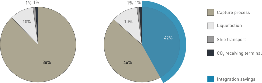
Figure 6: Distribution of the required energy input along the CCS chain with single capture plant at Fortum Oslo Varme. The left diagram shows energy input without any heat integration while theright diagram shows the energy input with heat integration.
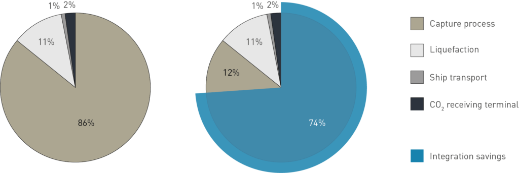
Figure 7: Distribution of the required energy input along the CCS chain with single capture plant at Heidelberg Materials. The left diagram shows energy input without any heat integration while the right diagram shows the energy input with heat integration.
Regulations
As CCS deployment is still at an early stage, government agencies and regulatory authorities in most countries have limited experience with CCS projects. For the transport and storage part in particular, novel CCS regulations and existing regulations applied in the context of CCS for the first time have triggered the need for additional efforts, both from the project and from the authorities. In order to avoid delays it has been important to keep the dialogue between the parties involved transparent and open.
The industrial partners and Gassnova have worked closely with the regulatory authorities to build knowledge and insight, identify potential issues early on, ensure alignment between governmental agencies, etc.
Observations concerning some of the regulations:
- The EU Directive on the geological storage of carbon dioxide (CCS Directive 2009/31/EC) was implemented in national Norwegian regulations in 2014 (“Forskrift om lagring og transport av CO2 på sokkelen”). These CO2 storage regulations were closely modelled on the existing petroleum regulations but is applied for the first time in Longship:
- The CO2 storage operations at the Sleipner and Snøhvit fields were already up and running when the new regulations came into place. These operations were found to be compliant and have continued to operate under the new rules.
- The Longship storage site is the first CO2 storage site in Norway to be fully permitted and licenced under the new rules. It will be returned to the state after its operational lifetime is complete and a period of subsequent compliance monitoring has established the long-term stability and fate of the CO2 plume in the reservoir intervals.
- Details surrounding the monitoring programme and the acceptance criteria that the government will apply with respect to long-term liability are defined within the Plan for Development and Operation (PDO) that Northern Lights has submitted to the Norwegian Petroleum Directorate. Although the timing and criteria for handing the storage back to the state remains to be agreed, sufficient clarity has been provided for the Northern Lights partners to take their FID’s.
- EU ETS (Directive 2003/87/EC) are tailormade for CCS chains where the captured CO2 is transferred to a storage facility either directly or via a pipeline. Other transport solutions, e.g. ship, truck or train, are not explicitly covered by the present regulation. In this project the regulation has been interpreted to mean that CO2 is geologically stored when it is received at the onshore terminal. The European Commission has in a letter to the Norwegian Ministry of Climate and Environment confirmed that shipping of CO2 is allowed under the ETS.
- The London Protocol aims to protect the marine environment by prohibiting unregulated dumping of waste, and it prohibits cross-border transport of CO2, even for the purposes of geological storage offshore. This prohibits storage of CO2 from European sources in Norway, with a damaging effect on the idea of shared storage infrastructure. To address this barrier, Norway and the Netherlands proposed a resolution that was accepted by the IMO in 2019, making it possible to establish agreements that allow cross-border transport of CO2 for the purpose of geological storage.
No regulatory showstoppers have been identified for Longship. Development of the capture plants follow regulatory processes that are well known to the Due to the novel elements in the Norwegian implementation of the CCS Directive (“Lagringsforskriften”), it has been necessary for Northern Lights to work more closely than normal with the authorities to achieve effective and timely approval processes. Flexibility has been required from all parties involved.
EU ETS regulation currently states that CO2 must be transferred to a pipeline or facility directly connected to a geological storage for the capture operator to reduce the reported emissions. It has thus been necessary to regulate the change of ownership of the CO2 at the interface between the capture plant and the ship in the state support agreements.
If CO2 is to be captured and stored in different countries, it is necessary to establish an agreement between the two countries involved in order to satisfy the London Protocol. It is important to address this issue as early as possible to ensure that the agreement is in place when the CO2 is ready for cross- border transport.
Norwegian fiscal regulations and EU ETS regulations seem to be sufficient to make a CCS chain operable in term of CO2 1–1.5% accuracy in volume measurements is required, and because there is no loss of CO2 from the transport ship, CO2 received by the receiving terminal can be counted as “stored”. The stored volume of CO2 per ship load will be available for the capture site for yearly report on EU ETS.
Costs
The cost of maturing the capture part of the project from feasibility study through FEED study, including the waiting period after the concept study and the interim phase after FEED, amounts to 6–8% of the estimated investment cost for each capture plant (sum of state support and contributions from the industrial partners).
The estimated investment cost for each part of the chain is given in Table 2.
The investment cost of the capture plants spread across the various building blocks is shown in Figure 8 (where contingency and owners costs are assumed to be shared by all building blocks). The percentages given are typical for Fortum Oslo Varme’s and Heidelberg Materials’s estimates with a maximum variation of +/- 5 percentage points.
The investment cost of transport and storage facilities spread across the various building blocks is shown in Figure 9 (where contingency, ownership costs, etc. are assumed to be shared by all building blocks).
For a CCS chain with both Fortum Oslo Varme and Heidelberg Materials, the net present cost per tonne of CO2 captured, transported and stored in the CCS chain will be NOK 1,280/ tonne*. Slightly more than 50% can be attributed to transport and storage.
Utilizing the full capacity of the storage facilities will bring the net present cost per tonne down to around NOK 940/tonne. Development of similar CCS chains may bring the cost down even further**.
The initial net present cost per tonne is affected by the overall framing of the project. The following aspects contribute to a higher cost per tonne than can be expected for future CCS chains:
- The project is based on retrofitting existing CO2 emission sources of relatively modest size.
- The distance between the capture sites and the storage site is long (700 km by sea).
- The overall concept is based on an onshore CO2 receiving terminal with subsea pipeline to increase robustness and make it easier to develop a “storage hub”.
- The project scope includes infrastructure for transport and storage that goes beyond what is needed to handle the CO2 from Fortum Oslo Varme and Heidelberg Materials only.
- The engineering contractors still have few references for the design and construction of CO2 capture plants in operation, and the designs are tailor- made, which suggests that prices are higher than for common industrial plants.
* From the Figure 5-4 final KS2-report dated 24th June 2020. Calculated by the method from the Norwegian Environment Agency with 25-year horizon, Heidelberg Materials and Fortum Oslo Varme combined.
** Potential for reduced costs for carbon capture, transport and storage value chains (CCS), DNV GL & Gassnova, 2019. Available at ccsnorway.com/
The extra capacity in the CO2 pipeline and receiving terminal comes at a relatively low additional investment cost:
- The cost of laying an offshore pipeline is similar up to a point where a larger pipe-laying vessel is needed. The increased cost of the pipeline itself is to some extent counteracted by less installation work needed (e.g. rock- dumping).
- Due to the batch nature of the transport system, it is primarily the capacity of the injection pump at the CO2 receiving terminal that needs to be increased to allow a higher throughput.
Although the capture technology is an important building block in a CO2 capture plant, it typically only represents a quarter of the total capture plant investment cost. Utility and support systems and preparation for transport (compression, liquefaction, conditioning and interim storeage) each represent as much as 33-34% of the capture plant investment cost and should receive attention early on.
| Investment cost MNOK | Operating cost MNOK/year | |
|---|---|---|
| Capture plant – Fortum Oslo Varme | 4090 | 224 |
| Capture plant – Heidelberg Materials | 3103 | 117 |
| Transport and storage facilities – Northern Lights (*) | 7300 | 364 |
Table 2: Estimated investment cost for each part of the CCS chain (in MNOK-2020 represented by P50 estimates from KS2 report).
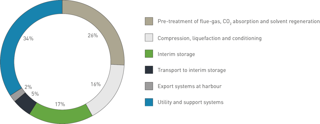
Figure 8: Estimated investment cost spread across the various building blocks in the capture plants, typical values from Fortum Oslo Varme and Heidelberg Materials.
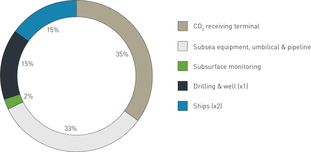
Figure 9: Estimated investment cost spread across the physical elements of the transport and storage facilities.
Other key learnings related to the project development
Some of the learnings aggregated during the development of Longship are related to more specific topics than those presented in the previous pages. Four such key learning points are presented below.
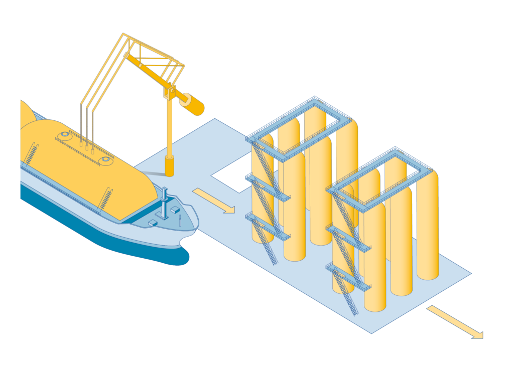
It is possible to design liquid CO2 transport ships as typical LPG-type carriers (“fully pressurized” liquefied gas carriers), with a few adjustments. The ship design developed for the project has a cargo capacity of up to 7,500 m3 (for liquid CO2 at approximately 15 barg). This will allow competitive bids when using existing shipbuilding
The HSE activities and practices used in typical industrial projects have been well suited for this kind of project (HAZID, HAZOP, ENVID, BAT, ). No significant challenges specific to CO2 have been identified. However, the particular properties of CO2 will require special attention, e.g. that it is heavier than air and therefore will fall to the ground and may accumulate at low points.
Issues related to the specific properties of CO2 should be addressed early in the concept selection phase and be kept in mind through the subsequent design They will typically impact material selection, zone classification, flow assurance, release and dispersion behaviour, etc. For industries that are used to handling hydrocarbons it may be an added challenge to simplify design to take advantage of the fact that CO2 is not flammable.
It is feasible to use tanker trucks as part of a CCS chain to connect a capture site with its export terminal (or hub). The distance by road between Klemetsrud and the Port of Oslo is 14 km and truck transport is preferred over a pipeline by Fortum Oslo Varme. A solution with trucks has fewer risks related to zoning processes and geological conditions, although the operating costs will increase rapidly with distance. At least three different potential suppliers for the transport service have been identified by Fortum Oslo Varme, showing that this service is commercially available.