
5. Regulations applied and solutions under development
Applying the legal framework on an industrial CCS chain for the first time, requires practical clarifications and solutions. The requirements in the legal framework must correspond with the existing technical solutions and vice versa. For instance, measuring the amount of CO2 is a precondition for transferring the responsibility of the CO2 from one partner to another in the CCS chain. Always knowing who is responsible is also a necessity. Likewise, making sure that CO2 is safely stored, requires monitoring of the storage site for decades. In the Sections below a description of how this is sorted out for Longship is given.
5.1 Transfer of responsibility for CO2 in the Longship CCS chain
The purpose of CCS is to eliminate CO2 emissions to the atmosphere for climate purposes. It is therefore important to monitor the amount of CO2 captured, transported and stored and any potential leakage of CO2 in the CCS chain.
In this section “responsibility for CO2” means that the industrial partner is responsible for monitoring and reporting any leakage of CO2 in the CCS chain and for submitting allowances under the ETS. Measuring the amount of CO2 transferred from one partner to another is a prerequisite for transferring the responsibility. For measurement methods refer to Section 5.2.
Prior to and in parallel with the planning of the Longship project the Norwegian Government has been working to clarify how the EU legislation, which has never been applied to a CCS project like Longship before, should be interpreted.
Longship is complicated in a regulatory sense because it includes CO2 from both fossil and biogenic sources, CO2 from the EU ETS and non-EU ETS sectors, and transport of CO2 by ship and trucks.
The Norwegian Government sent a letter49 to the EU Commission in July 2019, requesting legal clarifications related to the ETS Directive18 and the Monitoring and Reporting Regulation20. The EU Commission replied in a letter of 27. July 202050.
Ship transport of CO2 is not subject to the EU ETS, and during the planning phase it was unclear how CO2 transport by ship should be regulated. This issue was addressed in the letters cited above. According to a Norwegian interpretation of the Monitoring and Reporting Regulations20 the capture facilities will be able to subtract CO2 from their emissions accounting when CO2 is transferred from the ship to the reception terminal.
The European Commission endorsed this interpretation, and the following was stated in its reply letter:
“Transfer of captured CO2 to a ship or a truck does not prevent the right to subtract the CO2 when it is later on transferred from the ship or the truck to a pipeline transport network or directly to a storage site. When that later transfer from the ship or truck to the network or storage site is completed, the capturing installation can subtract the CO2 according to Monitoring and Reporting Regulation20 Article 49 (a) (ii) or (iii).”
This means that Heidelberg Materials (subject to EU ETS) will be able to subtract allowances when the CO2 has entered the receiving terminal in Øygarden and when Heidelberg Materials has received a certificate for the amount of CO2 delivered, issued by Northern Lights. Heidelberg Materials will not be able to subtract allowances for leaked CO2 during transport.
During the negotiations with the state, Heidelberg Materials made it clear that it was unacceptable to risk a financial loss due to leakage of CO2 from a ship Heidelberg Materials did not operate itself. Northern Lights and the State will therefore cover the costs related to leakage of CO2 from the ship, according to an agreed cost sharing ratio. Another issue addressed in the above-mentioned letters was subtraction of CO2 from biological origin.
In the letter from the Norwegian Ministry the following approach was proposed:
“The captured CO2 may – regardless of its origin (fossil or bio) – be subtracted as long as it does not exceed the operator’s total amount of produced fossil CO2 from the relevant installation. If the operator captures more CO2 than the total production of fossil CO2, the captured CO2 exceeding this number cannot be subtracted.”
The EU Commission replied with the following statement:
“…the Commission does not agree that captured CO2 from biological origin may be subtracted from the emissions of the installation. Indeed, there is no legal ground in the ETS Directive that could support this, and Article 49 (1) of the Monitoring and Reporting Regulation20 makes it clear that this is not possible (“The operator shall subtract from the emissions of the installation any amount of CO2 originating from fossil carbon […]”). However, it seems that other instruments could address the issue of and create incentives for bio-energy with carbon capture and storage in a more efficient way.”
Heidelberg Materials’s (subject to the EU ETS) emissions stem from both fossil and biogenic sources. For Heidelberg Materials this ratio is 87/13. Heidelberg Materials will capture approx. 50 per cent of its emissions. When the CO2 is captured, it is assumed that the proportion of fossil/bio is the same as for the total emissions from the factory. However, although it is possible to estimate the amount of biogenic CO2 captured and stored from Heidelberg Materials, they will neither be able to subtract bio-CCS within the EU ETS nor to receive emission allowances for such storage.
This illustrates that the EU ETS is not designed to create incentives for bio-CCS. To our knowledge, this issue related to bio-CCS is still being discussed within the EU.
Apart from the ship transport, all the Northern Lights (NL) activities (receiving terminal, pipeline, injection well and storage site) are subject to the EU ETS. When the CO2 enters the Northern Lights storage network in Øygarden, the CO2 – both the fossil and biogenic part – is regulated. Northern Lights is responsible for any leakage. The costs related to potential leakage is covered by Northern Lights and the State according to an agreed cost sharing ratio. It is unclear whether a leakage of sustainable biogenic CO2 can be counted as zero or not within the EU ETS if a leakage should occur from the storage site. For potential revenue from voluntary markets separate reporting rules may apply for relevant CO2 volumes.
| CO2 origin | Capture | Ship transport | Storage network | |
|---|---|---|---|---|
| Current regulations | Fossil CO2 | Heidelberg Materials (EU ETS / new combustion tax) | Heidelberg Materials (EU ETS) | NL (EU ETS) |
| Biogenic CO2 (sustainable) | Heidelberg Materials (EU ETS, counted as zero) | Heidelberg Materials (EU ETS, counted as zero) | NL (EU ETS, counted as zero?) | |
| State aid agreement | Fossil CO2 | Compensation from the state for captured CO2 | NL and the state cover the costs related to leakage | NL and the state cover the costs related to leakage |
| Biogenic CO2 | Compensation from the state for captured CO2 | N/A | NL and the state cover potential costs related to leakage |
Table 03: Heidelberg Materials – responsibility for leakage in the CCS chain and the financial compensation in the state aid agreement
Celsio is not subject to the EU ETS. Its emissions stem from combustion of both fossil and biogenic sources. For Celsio this ratio is 50/50. Celsio will capture approx. 90 per cent of its emissions.
As for Heidelberg Materials when CO2 is captured, it is assumed that the proportion of fossil/bio is the same as for the total emissions from the factory. A carbon tax on waste incineration was introduced in 2022. The tax is only relevant to the part of the emissions produced by combustion of fossil sources. Celsio will not have to pay the tax for emissions that are captured and stored.
Celsio’s CO2 will be transported by truck to intermediate storage at the Port of Oslo. From there the CO2 will be loaded onto the ship, operated by Northern Lights. Neither the CO2 truck transport nor the CO2 ship transport are currently regulated under the EU ETS.
As explained above, all the Northern Lights (NL) activities except ship transport are subject to the EU ETS. When the CO2 from Celsio enters the Northern Lights storage network in Øygarden, all the CO2 is regulated under the ETS in the same way as described for Heidelberg Materials above.
| CO2 origin | Capture and truck transport | Ship transport | Storage network | |
|---|---|---|---|---|
| Current regulation | Fossil CO2 | Celsio (new combustion tax) | Not regulated | NL (EU ETS) |
| Biogenic CO2 (sustainable) | Not regulated | Not regulated | NL (EU ETS, counted as zero?) | |
| State aid agreement | Fossil CO2 | Compensation from the state for captured CO2 | NL and the state cover the costs related to leakage | NL and the state cover potential costs related to leakage |
| Biogenic CO2 | Compensation from the state for captured CO2 | N/A | NL and the state cover potential costs related to leakage |
Table 04: Celsio – responsibility for leakage in the CCS chain and the financial compensation in the state aid agreement.
Additional issues related to potential new CO2 volumes to Northern Lights:
The only potential revenue stream for Northern Lights during the 10-year operating period is the tariff paid by new customers, the so-called “third-party volumes”. Northern Lights will manage the surplus capacity in the storage network and keep the revenue (limited upwards in the state aid agreement).
The responsibility for the CO2 delivered to Northern Lights’ (NL) ships from new customers in Norway and abroad will in principle be regulated in the same way as the responsibility for the CO2 from Heidelberg Materials and Celsio. The fact that ship transport is not included in the EU ETS means that the capture operator is responsible for leakage of CO2 during ship transport even though the ships are operated by another company.
However, the financial loss that results from a potential leakage during transport, can be regulated in private legal contracts between the operators. Despite this possibility, not including ship transport under the EU ETS is seen as an important barrier to cross-border transport of CO2. Revision of the EU ETS Directive14, including a proposal of including all forms of transport of CO2 for permanent storage51 in the ETS, is however ongoing.
It is a complicating factor when CO2 is transported across borders. In addition to define the responsibility at a commercial level, there is a need to define the responsibility at a country level. At what point is the responsibility for leakage of CO2 during transport transferred from one country to another? This must be defined in the bilateral agreement between the states. This needs to be in place before a commercial agreement between a new customer and Northern Lights can be concluded (read more about the London Protocol14 in Section 4.5).
| CO2 origin | Capture | Ship transport | Storage network | |
|---|---|---|---|---|
| Current regulation | Fossil CO2 from ETS | Capture operator | Capture operator | NL (EU ETS) |
| Biogenic CO2 (sustainable) from ETS | Capture operator (counted as zero) | Capture operator (counted as zero) | NL (EU ETS, counted as zero?) | |
| Fossil CO2 from non-ETS | Not regulated | Not regulated | NL (EU ETS) | |
| Biogenic CO2 from non-ETS | Not regulated | Not regulated | NL (EUETS, counted as zero?) | |
| Proposed regulation | Fossil CO2 from ETS | Capture operator | NL | NL (EU ETS) |
| Biogenic CO2 (sustainable) from ETS | Capture operator (counted as zero) | NL | NL (EU ETS, counted as zero?) | |
| Fossil CO2 from non-ETS | Not regulated | NL | NL (EU ETS) | |
| Biogenic CO2 from non-ETS | Not regulated | NL | NL (EU ETS, counted as zero?) |
Table 05: Third-party-volumes – responsibility for leakage under current and proposed regulation under the EU ETS.
5.2 CO2 measurement in the CO2 transport chain
The measurement and inventory of the transported CO2 is set up to meet the necessary commercial and regulatory requirements. The Monitoring and Reporting Regulation20 requires a maximum uncertainty in the measurement system when CO2 is transferred between installations.
Both CO2 quality and quantity are measured several places along the chain in the Longship project. The purpose of most measurements is process control. However, the total volume of CO2 inventory on the ship is defined for transfer between parties. This is measured twice: first when the CO2 is transferred from the capture site to the ship, and then before the CO2 is transferred from the ship to the receiving terminal in Øygarden (ref. point 3 and 4 in figure 04). For responsibility for potential leakage, refer to Section 5.1.
The state aid agreement between the capture sites and the Norwegian State specifies that capture sites will be compensated for the volume of CO2 received by the ship and corrected to -26°C (ref. point 3 in figure 4). This is done by the ship’s Custody Transfer Measurement System (CTMS) which measures the change in CO2 liquid level in the ship’s CO2 tanks, compensated for CO2 composition, pressure, temperature, trim and list. The state aid agreement requires the capture sites to measure the density of liquid CO2, which can be used to calculate the mass of liquid CO2 loaded onto the ship. The total accuracy of the agreed quantity measurement system (the CTMS) has been estimated to be well below 2,5% accuracy, which lays within the requirement in the Monitoring and Reporting Regulation20. This principle of quantity measurement is similar to the system used for trading of other liquified gases as e.g. LPG. The Longship partners will follow the same regime for 3rd party verification at 36-month intervals.
CO2 quantity measurements
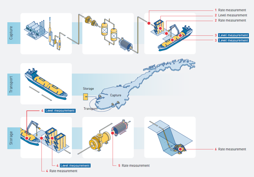
at the capture site, ship transport and interim storage, pumping and injection into well. The figure shows where the CO2 is
measured in the chain. The inventory transfer of CO2 is based on tank level measurement (blue boxes).
| No in figure 04 | Description |
|---|---|
| 1 | Amount (in cubic metres) of CO2 liquefied and transported in the pipe to storage tanks to be measured continuously with flow meter (ultrasonic). |
| 2 | Amount (in cubic metres) of CO2 exported from Heidelberg Materials to be calculated from measurements of storage tank levels at start and end of ship loading operation. Measurement of flow rate will most likely enter into the calculation, if deemed accurate enough. |
| 3 | Amount (in cubic metres) of CO2 loaded onto the ship (docked at Heidelberg Materials) to be calculated from measurements of ship tank levels at start and end of ship loading operation. This is the formal determination of the volume of CO2 transferred from Heidelberg Materials to Northern Lights in the state aid agreements. |
| 4 | Amount (in cubic metres) of CO2 discharged from the ship (docked at the receiving terminal) to be calculated from measurements of tank levels (both ship cargo tanks and interim storage tanks) at start and end of discharge operation. Northern Lights will evaluate use of operational flow meters, but not for accounting/custody transfer (in Longship). |
| 5 | Amount of CO2 injected to be measured continuously with a flow meter. This measurement, together with the subsea measurement, will be important for verifying the integrity of the pipeline. |
| 6 | Amount of CO2 entering the reservoir to be measured continuously with a subsea flow meter. |
Table 06: The table gives a brief description of the main quantity measurements in the Longship chain.
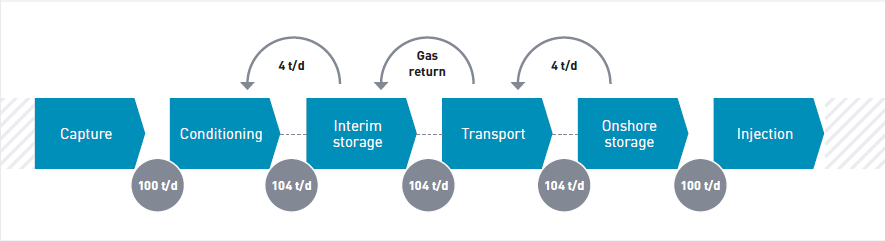
Gas return
CO2 storage/transport tanks cannot be drained to full vacuum and introducing other gases to displace the CO2 would pollute the next CO2 batch. The tanks will therefore contain gaseous CO2 at approximately equal pressure and temperature when emptied. As liquid is drained from one tank and filled into another tank, gaseous CO2 will flow the opposite way (in a dedicated pipe/pipeline). The mass of gaseous CO2 flowing is approximately 4% of the mass of the liquid CO2, due to the difference in density.
As the gaseous CO2 is liquefied together with the CO2 that has just been captured, the rate of liquid CO2 will therefore be increased by 4%, as shown in the outline diagram in Figure 05. If e.g., 100 tonnes/day is captured from flue gas, liquefied and transferred to interim storage vessels, the volume of the 100 tonnes will displace an equal volume of gaseous CO2, which is approximately 4 tonnes. These 4 tonnes of gas return will also have to be liquefied, so the liquefaction must be designed for 104 tonnes/day. The effect applies to every tank the liquid CO2 is transferred to, and the ship will also have to transport 104 tonnes.
CO2 specification
The CO2 specification in the Longship project has been agreed between the parties and is considered to be quite strict. For the transport and storage operator, it will reduce the risk for corrosion etc. to have the CO2 stream as pure and dry as possible. For the capture operator, purifying the CO2 may be costly. However, in the Longship project the CO2 is liquefied and therefore meets the CO2 specification set.
The CO2 volume is almost 100% pure CO2. The following specification governs the CO2 in the Longship project52. Design Basis for the CCS Chain’ rev. 5.2, 12.03.19.
Table 07: CO2 specification.
Note: Non-condensable gases are components that, when pure, will be in gaseous form under the given thermodynamic conditions. The content of non-condensable gases will be limited by the actual solubility in the liquid CO2 in the interim storage tanks at the capture plants.
| Component | Concentration, ppm (mol) |
|---|---|
| Water, H2O | ≤ 30 |
| Oxygen, O2 | ≤ 10 |
| Sulphur oxides, SOx | ≤ 10 |
| Nitric oxide/Nitrogen dioxide, NOx | ≤ 10 |
| Hydrogen sulphide, H2S | ≤ 9 |
| Carbon monoxide, CO | ≤ 100 |
| Amine | ≤ 10 |
| Ammonia, NH3 | ≤ 10 |
| Hydrogen, H2 | ≤ 50 |
| Formaldehyde | ≤ 20 |
| Acetaldehyde | ≤ 20 |
| Mercury, Hg | ≤ 0.03 |
| Cadmium, Cd Thallium, Tl | ≤ 0.03 (sum) |
5.3 Monitoring
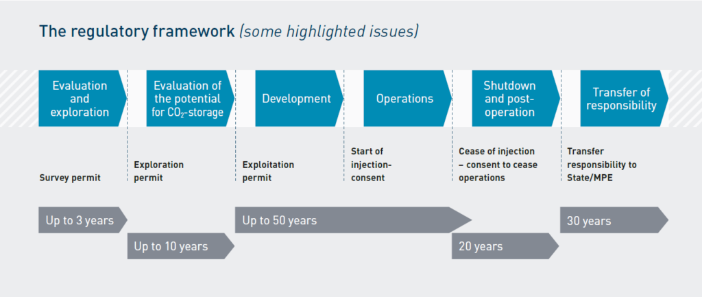
In Section 3.1 the regulatory framework for CCS was addressed, and in Section 3.1.1 the licencing system and regulations used this far in the Longship project was described. Monitoring requirements involves long-term commitments. The need, requirements and time for monitoring can change in the course of a storage project’s life-time; so although a monitoring plan needs to be submitted to obtain a permit for storage, this can later change (especially with regards to the timeframe of when CO2 can be considered safely stored). This represents potential uncertainties for the storage operator (Section 4.4). Northern Lights submitted a monitoring plan according to requirement of the legal framework, and this Section addresses the demand to a monitoring plan according to the CCS Directive19 and Storage Regulations21 and highlights the future obligations.
CCS is a climate mitigation tool, and the aim of CO2 storage is consequently to prevent the CO2 from entering the atmosphere. Monitoring the behaviour of the CO2 beneath the seabed and confirming that the CO2 stays underground for the foreseeable future is therefore important. However, the long timespan of the monitoring may impose a financial uncertainty on the storage operator.
A monitoring plan is a prerequisite for obtaining the necessary permits for underground injection. Generally speaking, all requirements to measuring and monitoring are covered by the CCS Directive19, transposed into Norwegian law through the Storage Regulations21, except the quantification of emissions, which is covered by the EU ETS alone.
The legal requirement for monitoring in Norway is based on Section 5.4 of the Storage Regulations21, which adheres directly to the guidance set out in the CCS Directive19, Article 13 and Annex II, which describe the requirement for monitoring of the injection facilities, storage complex and surrounding environment, and the details required in the monitoring plan. Section 5.4 of the Storage Regulations21 are referred to in figure 06.
The monitoring should be based on a monitoring plan produced by the operator in accordance with the requirements in Annex II to these Regulations, which the Ministry of Petroleum and Energy has approved pursuant to Section 5-2.
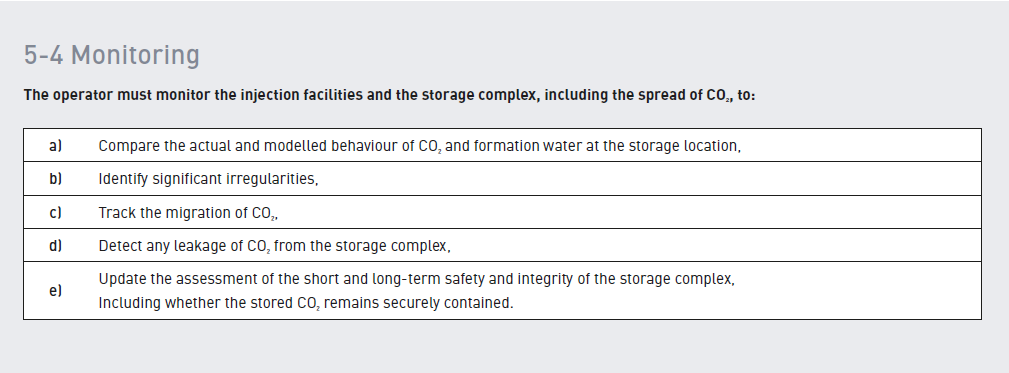
The plan should be updated in accordance with the requirements in Annex II to these Regulations, and in any case every five years. This is to make any changes to the risk assessment concerned with leakage and in the interests of the environment and human health, in light of new scientific knowledge or technological improvements. Updated plans are conditional on approval from the Ministry of Petroleum and Energy pursuant to Section 5-2.
The demands for monitoring will vary in the different stages of a CCS project (ref. figure 07), from the baseline measurements in the initial phases of a storage project, over the comparative and control measurements during the operative phase to constant observatory monitoring after end of the project and will therefore require the use of different methodologies. It is important to understand that there is no single methodology that allows a complete quantitative analysis of potential CO2 leakage from an underground storage site.
The operator is responsible for monitoring the storage site during the operational phase on the basis of the monitoring plan, but also in the period following closure until the storage site has been transferred to the state. In the event of leakages of CO2 or significant irregularities, the operator must notify the state and take the necessary corrective measures. The state may also take corrective measures itself and recover the costs from the operator, and it has a duty to do so if the operator fails to fulfil its obligations.
Further, it is a requirement that the monitoring technologies put in place should be based on “best practice available at the time of design”. How a technical monitoring, measuring and verification framework should be put in place and structured, and which technologies are available, are dependent on the geological setting of the specific storage site. The elements of any monitoring plan, its objectives and the technologies used, are therefore site-specific and risk-based.
In practice, this means that the monitoring technology employed may change during the operational phase of the site and that the competent authority might, at a later stage, make use of other specific technologies or measurement methods that were not in the original monitoring plan (for example, at Sleipner the monitoring methods were changed and adapted over time). The requirement for how often the methods are to be performed and reported is not set out in the directives.
The overall requirements can be loosely subdivided into three monitoring categories: containment assurance, conformance assurance and contingency monitoring in the event that the former two categories are not met. The risks of potential leakage points will be identified, and a number of elements are evaluated with regards to the three subcategories in a risk assessment. A general (but not exhaustive) table of elements are highlighted in Figure 08.
The Northern Lights – Storage Complex Monitoring Plan53 describes the scope of Northern Lights monitoring for the Aurora CO2 storage site to prevent and mitigate leakage risk exposures, and to ensure regulatory compliance with respect to storage of CO2 in the subsurface strata according to the Storage Regulations21 and the Pollution Regulations22. The plan was accepted by the Norwegian Environmental Agency and the Ministry of Petroleum and Energy as part of the process of obtaining the permit for injection and storage of CO2 (Section 3.1.1).
The planned subsurface monitoring consists of in-well monitoring of pore pressure and temperature, and 3D seismic (active and passive) monitoring of the subsurface. The planned monitoring is tailored around conformant behaviour, with a second monitoring being triggered in case of non-conformance with a contemporaneous change in injection. The plan is based on an extensive risk analysis based on the site’s unique geological characteristics and the best technological methods to meet the need for monitoring.
The monitoring plan will be updated based on data collected from the monitoring plan activities, and in any case every five years to take account of changes in the assessed risk of leakages, changes in the assessed risks to the environment, new scientific knowledge and improvements in the best available technology. If significant non-conformance between observed and predicted behaviour is detected, the 3D model will be calibrated/updated, and an updated plan will be re-submitted for approval.
| Operational | Plume | Pathways | Environmental (Leakage) |
|---|---|---|---|
| ■ Injection Well Control ■ Pressure & Temperature ■ Composition ■ Quantification | ■ Calibrate Models ■ Migration ■ Kinetics ■ Trapping Mechanisms ■ Trapping Efficiency ■ Pressure ■ Water behavior | ■ Caprocks ■ Faults & Fractures ■ Wells ■ Aquifers | ■ Leak detection ■ Leak quantification ■ Emissions/ETS impact ■ Safety & Environmental impacts |